Index of current HKS products covered
Oct 25 1998 - 1. HKS Super Power Flow, open element foam air filter
Oct 25 1998 - 2. HKS Speed Limit Defencer, removing the 180kph limit
Feb 01 1999 - 3. HKS Air Fuel Regulator, calibrating the air-fuel ratio
Air Fuel Regulator (AFR)

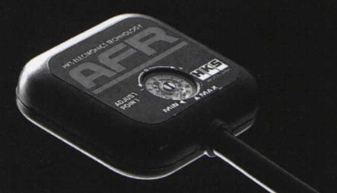
HKS' Air Fuel Regulator (AFR) is a device that modifies the air-fuel
ratio of the engine. AFR works by intercepting the air-flow sensor signal
(which is a pressure-based MAP sensor in Hondas) and modifying that signal
before feeding it to the ECU. This modified signal will in turn cause
the ECU to change the air-fuel ratio based on the modified signal. To
understand the working principle of the HKS AFR, it then becomes necessary
to first understand the working logic of Honda's PGM-Fi fuel injection
system.
HONDA PGM-Fi Operating Logic
PGM-Fi controls air-fuel ratio by varying the opening duration
of the fuel injectors. The rate of fuel fed by the injectors
is constant so a longer or shorter opening duration
will increase or decrease the amount of fuel being fed into the cylinders
(respectively). There have been a lot of misconceptions and
misinformations on the working logic which PGM-Fi uses to determines this
injector opening cycle and TOV-A is very grateful to Rennie for the
following description.
|
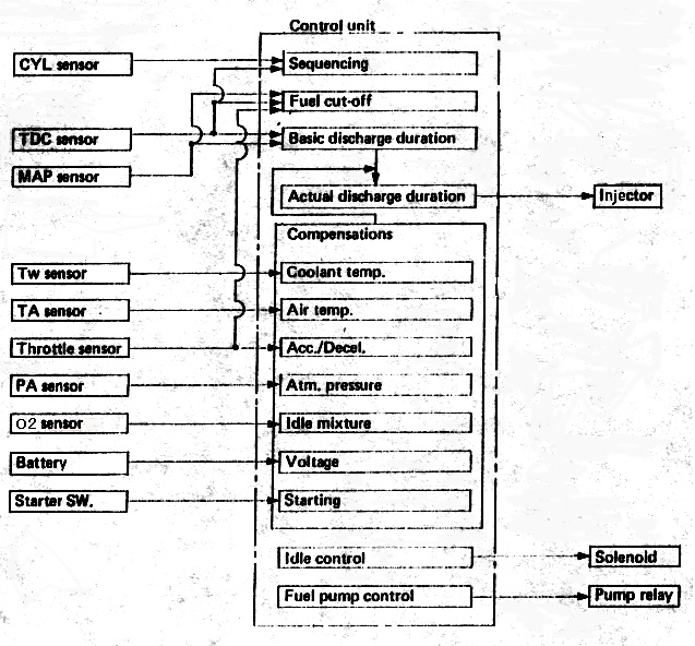
On the right is a block diagram of PGM-Fi's operating logic for
determining injector opening duration. The basic algorithm is :
first determine the base opening duration from a fuel map, then
compensate for a set of engine and atmospheric conditions
which are measured by various onboard sensors.
The base PGM-Fi fuel map is a three axes, X-Y-Z type map.
The two independent axes are readings from
the TDC and MAP sensor, ie engine RPM and air-flow. From these two
parameters, PGM-Fi reads a base injector opening duration value
off the map. This base value is then modified using the various
sensor readings. Some of the sensors
are used only during certain situations, eg during engine
cranking. There are also different priorities assigned to each parameters
which again varies depending on situations.
|
 |
An important point to note is that although PGM-Fi measures a lot of
conditions, it does not measure all atmospheric conditions. For
example there is no air humidity sensor.
Headroom, Open-Loop and Closed-Loop Operations
A standard PGM-Fi program is used for each engine design, eg
JDM B16A. The base fuel map is programmed using a set of 'base'
values for various parameters like air temperature, pressure, and other
various other measured engine/atmospheric conditions. From these
base conditions, actual amount of oxygen available for combustion will
vary according to air-flow as oxygen content per volume of air is assumed
to be constant. However, the actual oxygen content available per volume of
air will still vary slightly because of other unmeasured
atmospheric conditions like humidity, elevation above sea
level or even locality, eg countryside or city-center. Because of this,
Honda engineers used results averaged from a large sample of varying
conditions to create their base fuel map.
A similar process was also used to determine the trimming values used
when compensating the base injector opening duration for deviations of
sensor readings like air temperature and pressure from the base values.
One important design point of PGM-Fi is then the use of 'headroom'
(or safety margin) by Honda engineers. To ensure engine reliability, PGM-Fi
allows for worst case deviations from the average conditions used in the
program. Over-rich air-fuel ratios will cause fuel economy or engine
efficiency problems while over-lean ratios may cause detonation and
consequently engine damage. So PGM-Fi is designed to run slightly rich
for all deviations from the base average conditions used, including
the worst case conditions. As a result, the base fuel map, and then the
compensations for the trimming parameters are all designed to deliver
rich air-fuel ratios under all foreseeable operating conditions.
PGM-Fi operating logic also needs an explanation of what is called the
'open-loop' and 'closed-loop' operating mode for PGM-Fi. Closed-loop means
a feedback-loop mode. PGM-Fi works in closed-loop mainly during engine
idling. In closed-loop mode, PGM-Fi uses the signal from one critical
sensor, the O2 (or sometimes known as lambda) sensor to attempt to attain
an ideal air-fuel ratio of 14.7:1 (stoichometric ratio).
An O2 sensor operates by measuring
the amount of oxygen left in the exhaust gas. The amount of oxygen is a
good indicator of the combustion efficiency and a higher oxygen content
will suggest a lean condition and vice versa. O2 sensors are normally
mounted on the exhaust manifold (or sometimes called the extractors) and/or
catalytic converters (for cars equipped with them) and PGM-Fi uses
the O2 sensor reading to bump air-fuel ratio up or down until it gets
a reading indicating optimum combustion.
So during engine idling, the air-fuel ratio may initially fluctuate
up and down based on O2 sensor readings but should eventually settle to
a stable value corresponding to the ideal 14.7:1 ratio. PGM-Fi works in
closed-loop mode only during idle or very light accelerator openings.
From moderate to maximum throttle openings, PGM-Fi goes into an
open-loop mode. In open loop mode, PGM-Fi ignores the O2 sensor signal but
will still use the other sensor signals (air temperature and pressure,
TPS etc) to make compensations on the base injector opening values. However
for very heavy accelerator positions (indicated by large TPS values), PGM-Fi
now gives priority to engine RPM, MAP and TPS sensor readings. RPM and
MAP sensors will always be required since they are input parameters for
reading the fuel-map. But in open-loop mode, PGM-Fi no longer makes as
much compensation for other sensor readings, other than TPS sensor, as
in closed-loop mode.
When operating in open-loop then, PGM-Fi will usually be operating
in a rich-mode. This will be especially true for JDM vehicles when imported
directly from Japan into various countries (whether as used or new cars).
The PGM-Fi program will have been originally designed based on the
atmospheric conditions in Japan and they will almost certainly be different
from the countries into which the cars are imported. Even for truly
localized line-ups, a rich condition also normally prevail because
the PGM-Fi program would have been originally developed to accomodate for
the whole country or sometimes even an entire region and thus would again
be based on a large base of 'average' values.
Working Principle of HKS AFR
HKS' AFR intercepts the MAP sensor signal to the ECU and modifies it.
AFR will either increase or decrease the MAP signal strength by a single
fixed quantum value depending on the setting of a dial. This dial has 12
positions (also called 'clicks'). Position 6 is 'neutral' and passes the
MAP signal unmodified. The lower 5 positions reduces the MAP signal and
the remaining higher 6 positions increases the MAP signal. AFR intercepts
only the MAP signal and thus will adjust the MAP signal for all RPMs.
By trimming the MAP sensor value (up or down), AFR causes PGM-Fi to read
higher or lower air-flow and correspondingly more or less oxygen for
combustion. This will cause PGM-Fi to adjust the injector opening duration
thus indirectly changing the air-fuel ratio.
AFR works by exploiting the headroom used in the PGM-Fi program.
It is possible to reduce the headroom because we will be using our car in a
geographically restricted location and thus more stable atmospheric
conditions than those used to design the original program. Thus we use AFR
to calibrate our air-fuel ratio to a more exact value to match our
locality and this value will usually be different from the base averaged
value programmed into PGM-Fi. In addition the deviations from this value
will also not be as wide as what the PGM-Fi headroom is designed to
accomodate for because of the more stable atmospheric conditions.
Correctly setting the AFR will effectively calibrate the MAP signal to
the local atmospheric conditions and this allows extraction of
some untapped power from the engine by allowing the ECU to use a more
exact air-fuel ratio.
Since we typically will not know the exact conditions
under which the original PGM-Fi program is developed, the standard procedure
to determine the best AFR setting is through a dyno session.
A standard AFR tuning process will involve bumping the AFR adjustment
click by one click on either side of the neutral click 6 setting
and dynoing the resulting power gain/loss. The final setting
will be that where maximum power is obtained without any adverse
side-effects like knocking etc.
Rennie goes to great lengths to explain that the AFR does not directly
modify the amount of fuel fed into the engine, ie AFR does not touch
the injector output signals from the ECU and the ECU still has total control
over that signal. AFR modifies the MAP signal and that influences the
ECU to richen or lean the air-fuel ratio by detecting higher or lower
amount of air being fed into the engine. This is a very different
implementation. The ECU still has throttle position, engine RPM and the
other minor signals (engine temperature, O2 sensor output, etc) to
consider together with the modified MAP signal to determine the injector
opening duration. This is not exactly the same as modifying the actual
injector opening duration control signal.
One common criticism of the AFR is that it has only one adjustment point
for the entire RPM range. Compared to competing products with multiple rpm
point adjustments, it is suggested that AFR is limited in its ability to
tune engine power. This criticism is invalid. AFR is designed
to work with stock or mildly modified engines. Mild modifications means
the normal filter-exhaust type changes, ie those which improves
air-flow through the engine. Notice that AFR is effectively recalibrating
the air-fuel ratio to local atmospheric conditions and this calibration
is constant regardless of engine RPM (ie does not vary on engine RPM).
Therefore, AFR needs only a single adjustment point. This is
also the reason why it also works for stock engines.
For moderate to heavy
mods, eg camshaft changes or headwork, it may now be necessary to
adjust the actual air-fuel ratios differently across different parts of
the rpm-band. Now, AFR may no longer be as effective and the multi-rpm
adjustable devices like HKS GCC-2 or Field SFC-VTEC will be necessary.
Nevertheless, HKS maintains that the most accurate adjustment device
for such cases will remain those that actually modifies the injector
opening duration values, eg HKS FCON-4 or FCON-5 or an ECU change.
With a dynojet facility and a rich database of dyno-runs,
Aerotech supplied two dyno-runs of before and after results of installation
a HKS AFR to demonstrate its effectiveness.
 |
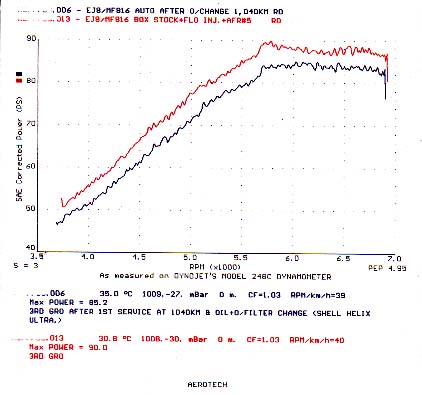
The AFR is installed on a brand new 1997 Malaysian Domestic
Market Civic EXi, using a 1.6lSOHC PGM-Fi engine and automatic transmission.
The engine is spec'ed to give 120ps at 6400rpm. The 1st run was done after
doing 1040km on the car (complete running in) and after the first service
which comprised engine oil change (Shell Helix), and oil-filter change.
This car dyno'ed at 85.2ps for the base run working out at a 29% power
loss due to peripherals and the automatic transmission.
The after run is with a HKS AFR set at click 5 (one point leaner air-fuel
ratio than stock) and with cleaned fuel injectors. The new power
is 90.0ps at the wheels or a 4.8ps increase. 90ps at the wheels works
back to 126.8ps at the engine, about a 5% increase. The fuel injector
cleaning gave slightly less than 1ps increase in max power. |
 |
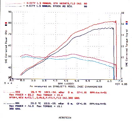
The AFR is installed on a Honda City 1.3EX manual. The City is a special
regional model for the South-East Asia market, conceptualized as a special
"people's car" by Honda. The base engine is spec'ed to produce 90ps at
6300rpm. The before run was on a totally stock engine and the after run
was with a HKS AFR set at click 4 (two points leaner than stock) and also
with cleaned fuel injectors. With no other changes, the final power
from the combination of AFR and cleaned injectors was 83.2ps from 76.9ps
at the wheels or a 6.3ps increase. 83.2ps works back to almost
98ps at the engine, or a 9% power increase over stock ! |

All JDM Honda models have an artificial 180kph top-speed limit.
This limit, existing even on the NSX Type-S, is implemented by Honda via
the engine ECU. The following
explanation of how the 180kph limit is implemented is
by kind courtesy of Rennie.
The Vehicle Speed Sensor (VSS) is a device attached to the transmission
that measures the car's speed via tracking the number of revolutions of
the wheels. The output of a VSS is in either sine wave, square wave or
in the form of pulse counts.
When the engine ECU detects the car is travelling at 180kph via the
VSS signal, it reacts in one of two ways. It will either stop 2 or more
injectors or it can cut the ignition (probably intermittently).
This reduces engine power output drastically, slowing down the car
until its speed drops below 180kph.
According to Rennie, in JDM cars, cutting off the VSS signal to the
engine ECU can lead to one of three conditions. One is the ECU will just
ignore the absense of the VSS signal and continue operating as normal.
In another, the engine simply won't start or will
die when gear is engaged.
The final condition is the ECU program, because it now cannot determine
how fast the car is travelling, goes into a backup safe mode
in which it runs the engine rich. This unnatural rich mode is undesirable
and will actually lead to a slight loss in engine power as well as oil
dilution (contamination of engine oil with petrol).
In Hondas, loss of
the VSS signal will cause the ECU program to go into the backup safe mode.
In addition, it will invoke a trouble code of 17 (for EF8/EF9 CRX/Civic
SiR) indicating 'faulty vehicle speed sensor'.
In the HPL archives, Doug MacMillion said that
cutting off the VSS signal will also stop the ECU from engaging the high
cam lobes for the B16A.
The HKS Speed Limit Defencer (SLD) device works by intercepting the
VSS signal and substituting its own signal to the ECU. This device has
four wires, two of them for power and ground and of the other two,
one receives the VSS signal and the other feeds a substitute signal
into the ECU. The simple diagram below illustrates the installation of
the HKS SLD.

 Temple of VTEC Asia


